
The following instructions detail how to flash the bootloader and application for the Audio Starter project.
Only required for software that can be updated using the SAM Flasher (ADZS-SC589-MINI)! Skip this step otherwise. See Software Compatibility
The bootloader allows for application reflash via the SAM Flash Tool depending on a pushbutton state. Note that this step requires you to identify which version of SAM hardware you have, as the script to use will change depending on the hardware version.
Follow the instructions below to flash the bootloader:
| 1. Identify if you have the SAM hardware version v1.4 (or earlier) or v1.5 or greater. The version may be printed on the silkscreen on the back. Additionally, v1.4 has is a green PCB, while v1.5 is a blue PCB. |   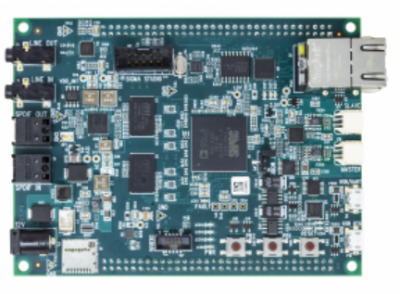 |
| 2. Prior to powering on the board, ensure that the JP1 jumper is set to position 1-2. Power on your SAM board and plug in the 12V Power Supply to the 12V connector. If the board is properly powered, the green LED9/PWR will light up. |   |
| 3. Connect the USB cable for the ICE-1000 or ICE-2000 to the PC and to the ICE. If the device is powered on, a green light will appear. | 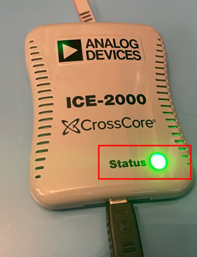 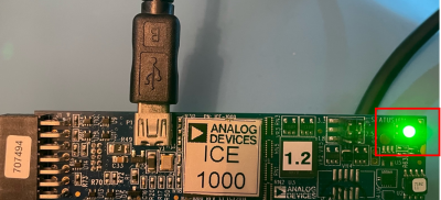 |
| 4. Connect the 10-pin header to the ICE and to the Debug Header on the SAM (labeled DEBUG) - noting that the header is keyed. |  |
| 5. Open the Git Bash application and navigate to <BOOTLOADER_PROJECT_ROOT>/bootloader/prebuilt |  |
| 6. Optional If using the ICE-1000: Open with your preferred text editor: boot0_hw_rev_1_4_cldp.bat and boot1_hw_rev_1_4_cldp.bat if your hardware is v1.4 or earlier or boot0_hw_rev_1_5_cldp.bat and boot1_hw_rev_1_5_cldp.bat if your hardware is v1.5 or greater and modify the -emu 2000 option to -emu 1000 to match the emulator in use. Save and close the files. |  |
| 7. At the command line, enter the command ./boot0_hw_rev_1_4_cldp.bat if your hardware is v1.4 or earlier or ./boot0_hw_rev_1_5_cldp.bat if your hardware is v1.5 or greater. Note that during program flash, the emulator LED will change from green to purple while the update is ongoing and will return to green once the update is completed. |   |
| 8. At the command line, enter the command ./boot1_hw_rev_1_4_cldp.bat if your hardware is v1.4 or earlier or ./boot1_hw_rev_1_5_cldp.bat if your hardware is v1.5 or greater. |  |
Only required for software that can be updated using the SAM Flasher (ADZS-SC589-MINI)! Skip this step otherwise. See Software Compatibility Note that this only needs to be done once, but MUST be done after flashing the bootloader in the previous step!
The CLD CDC Driver is a driver that lives on the PC that acts as an interface between a serial terminal, such as TeraTerm, or the SAM GUI Flash Tool. This driver is required for USB to Serial emulation and to be able to interact with the bootloader or application at run-time on the physical SAM hardware.
To install the CLD CDC Driver:
Only available for products that support SAM Flasher updates!
Follow the instructions below to flash the application via the SAM Flasher:
| 1. Power on your SAM board and plug in the 12V Power Supply to the 12V connector. If the board is properly powered, the green LED9/PWR will light up. |  |
| 2. Plug the USB Micro Type B side to the SAM board USB connector and the USB Type A side to a USB connection on the PC. Note that on SAM v2.1 HW this is the connection on the board labeled USB OTG | 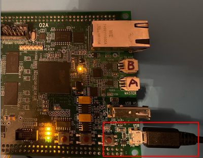 |
| 3. On the SAM board, press and hold buttons PB1 and PB2. While still holding PB1 and PB2, press RESET. Note that you do not need to hold reset. Resetting the board while holding PB1 and PB2 down will tell the bootloader to stay in the bootloader and await instructions for application flash. If this is successful, LED10 will blink, while LED11 and LED12 will remain off. |  |
| 4. Open the SAM Flasher Tool |  |
| 5. Select the Comm Port labelled SC5xx Communications Port. |  |
| 6. Select Load and navigate to the LDR that was generated during compilation. |  |
| 7. Select Update. The program Status will specify that it is erasing flash. Once it has completed, the program Status will specify that it has completed. You can close the SAM Flasher Tool after this. |   |
| 8. To enter the application, press the RESET button on the SAM again. If the application has properly loaded, LED10 will blink and LED11 will remain on. You will be able to additionally access the shell. |  |
Only available for products that support CLPD updates via Bootswitch!
Follow the instructions below for products which support CLPD updates via Bootswitch:
This section will explain how to flash an application with the CrossCore Serial Flash Programmer, ccsfp.exe.
| 1. Set the bootswitch to the position for “UART boot”. For example, on the SC584-EZLITE, set the rotary boot switch to position “7” for UART boot. For detailed info on boot switch positions, consult the schematic for your target board. If using the SC589-MINI, place the “BOOT MODE” jumper (JP1) to position 2-3. | 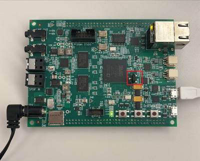 |
| 2. Power on your board and plug in the 12V Power Supply to the 12V connector. If the board is properly powered, the green PWR LED will light up. Location of LED will vary based on device. |  |
| 3. Plug a micro-USB cable from your PC into the USB/UART port on your evaluation kit. | 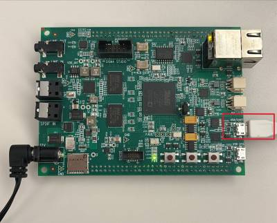 |
| 4. Open the “CrossCore Serial Flash Programmer” program included in the CrossCore Utilities package. This can be done either through the Windows Start Menu or by finding the executable at “C:\Analog Devices\CrossCoreUtilities-Rel1.7.1\bin\ccsfp.exe”, assuming a standard installation path. |  |
| 5. Select the Target board, Serial Port, and Baudrate to connect to your ADSP platform. The standard baud rate is 115200. Then select the .ldr file to flash to your target platform. SC589-MINI users should select the “SHARC Audio Module” for the target. Serial Port will differ for each individual kit, but should be the USB/UART connector on most kits. The correct COM port will show up as “Silicon Labs CP210x USB to UART Bridge”. |  |
| 6. Hit “Start” and verify a successful flashing process by viewing the status log. If you receive a message like “No autobaud response”, please verify that you are plugged into the “USB/UART” port of your evaluation board, and that you have set your device up for the proper Boot Mode. If not, reconfigure the Boot Mode and reset the power to your board to reboot. |  |
| 7. Set your boot mode back to the default on your target platform, then reset the power to your board to verify the application firmware starts correctly. |  |