The MAX31855PMB1 peripheral module provides the necessary hardware to interface the MAX31855 cold-junction compensated thermocouple-to-digital converter to any system that utilizes Pmod-compatible expansion ports. The MAX31855 performs cold-junction compensation and digitizes the signal from a thermocouple. Versions of it are available that operate with a K-, J-, N-, T-, R-, or E-type thermocouple.

This module is set up to operate with a K-type thermocouple. The data is output in a signed 14-bit, SPI-compatible, read-only format. This converter resolves temperatures to 0.25°C, allows readings as high as +1800°C and as low as -270°C, and exhibits thermocouple accuracy of ±2°C for temperatures ranging from -200°C to +700°C for K-type thermocouples.
When using the MAX31855 PMOD board, the 3.3 V power comes directly from the host board it is connected to. The power from the host is generally capable of providing up to 100 mA at 3.3 V; but for complete PMOD power specifications, please clickhere.
The device includes signal-conditioning hardware to convert the thermocouple’s signal into a voltage compatible with the input channels of the ADC. The T+ and T- inputs connect to internal circuitry which reduces the introduction of noise errors from the thermocouple wires.
Before converting the thermoelectric voltages into equivalent temperature values, it is necessary to compensate for the difference between the thermocouple cold-junction side (device ambient temperature) and a 0°C virtual reference. For a K-type thermocouple, the voltage changes by about 41µV/°C, which approximates the thermocouple characteristic with the following linear equation:
 where VOUT is the thermocouple output voltage (µV), TR is the temperature of the remote thermocouple junction (°C), and TAMB is the temperature of the device (°C).
The function of the thermocouple is to sense a difference in temperature between two ends of the thermocouple wires. The thermocouple’s “hot” junction can be read across the operating temperature range below for K type.
 The reference junction, or “cold” end (which should be at the same temperature as the board on which the device is mounted) can range from -55°C to +125°C. While the temperature at the cold end fluctuates, the device continues to accurately sense the temperature difference at the opposite end.
The PMOD interface is a series of standardized digital interfaces for various digital communication protocols such as SPI, I2C, and UART. These interface types were standardized by Digilent, which is now a division of National Instruments. Complete details on the PMOD specification can be found here.
The MAX31855PMB1 peripheral module can plug directly into a Pmod-compatible port (configured for SPI) through connector J1. Connector J1 provides connection of the module to the host. The pin functions and pin assignments adhere to the Pmod standard recommended by Digilent.


There are two device driver solutions that are provided for controlling the MAX31855PMB1:
The MAX31855PMB1 can be used with the MAX32655FTHR and MAX32650FTHR.
The following is the list of items needed in order to replicate this demo.
1. Connect MAX32655FTHR with the FTHR-PMD-INTZ. Note that MAXIM feather board should have stacking headers for feather board where the interposer board will be connected.
2. Connect MAX31855PMB1 to the FTHR-PMD-INTZ .
| MAX31855PMB1 | FTHR-PMD-INTZ SPI |
|---|---|
| Pin 1 (Chip Enable) | CS |
| Pin 2 (Not connected) | MOSI |
| Pin 3 (MISO) | MISO |
| Pin 4 (SCK) | SCK |
| Pin 5 (GND) | GND |
| Pin 6 (VCC) | VCC |
The final setup should look similar as shown below.

3. Power up the MAX32655FTHR by connecting it to your laptop using a micro-USB cable.
4. Open the file explorer. Drag-and-drop the pre-built hex file to the DAPLINK. If the transfer was not completed, update the firmware for the DAPLINK. Follow the steps here: https://github.com/MaximIntegrated/max32625pico-firmware-images/
5. Open PuTTY or other similar software. Check the Device Manager to set correct COM for the MAX32655FTHR. Set baud rate to 57600 when running max31855_maxim_basic_example_max32655.hex available in max31855_max32655.
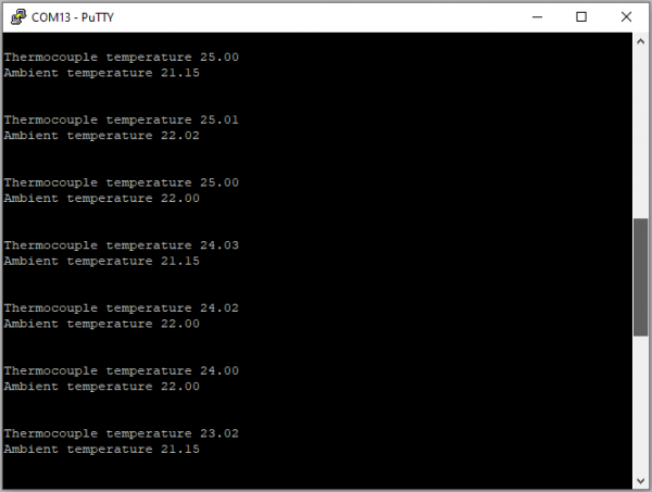
The expected output viewed in the PuTTY is shown below.

1. Using a 10-pin ribbon cable, connect the MAX32625PICO to the MAX32650FTHR.
 2. Connect MAX32650FTHR to the FTHR-PMD-INTZ.
3. Connect MAX31855PMB1 to the FTHR-PMD-INTZ .
| MAX31855PMB1 | FTHR-PMD-INTZ SPI |
|---|---|
| Pin 1 (Chip Enable) | CS |
| Pin 2 (Not connected) | MOSI |
| Pin 3 (MISO) | MISO |
| Pin 4 (SCK) | SCK |
| Pin 5 (GND) | GND |
| Pin 6 (VCC) | VCC |
The final setup should look similar as shown below.

4. Power up the MAX32650FTHR by connecting it to your laptop using micro-USB. Connect MAX32625PICO to your laptop as well.
5. Open the file explorer. Drag-and-drop the pre-built hex file to the DAPLINK. If the transfer was not completed, update the firmware for the DAPLINK. Follow the steps here: https://github.com/MaximIntegrated/max32625pico-firmware-images/
6. Open PuTTY or other similar software. Check the Device Manager to set correct COM for the MAX32650FTHR. Set baud rate to 57600 when running max31855_maxim_basic_example_max32650.hex available in max31855_max32650.
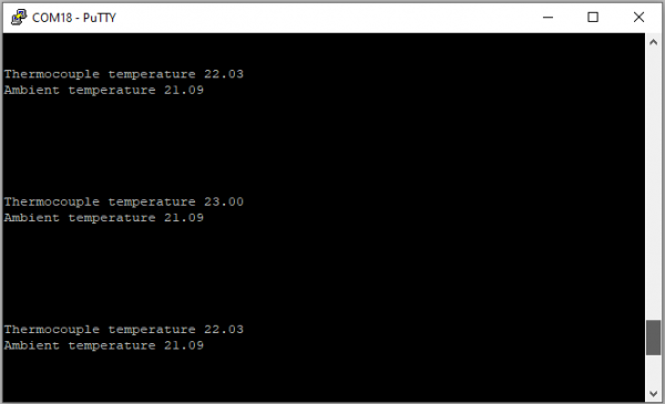
The expected output viewed in the PuTTY is shown below.

The Libiio is a library used for interfacing with IIO devices and is required to be installed on your computer.
Download and install the latest Libiio package on your machine.
To be able to connect your device, the software must be able to create a context. The context creation in the software depends on the backend used to connect to the device as well as the platform where the MAX31855PMB1 is attached. One platform is currently supported for the MAX31855PMB1: the MAX32655FTHR and MAX32650FTHR running the no-OS MAX31855 demo project. The user needs to supply a URI, which will be used in the context creation.
The iio_info command is a part of the libIIO package that reports all IIO attributes.
Upon installation, simply enter the command on the terminal command line to access it.
iio_info -u serial:<serial port>
Examples:
There are different commands that can be used to manage and control the device being used. The iio_attr command reads and writes IIO attributes.
analog@analog:~$ iio_attr [OPTION]...
Example:
analog@analog:~$ iio_attr -a -C
The iio_reg command reads or writes SPI or I2C registers in an IIO device. This is generally not needed for end applications, but can be useful in debugging drivers. Note that you need to specify a context using the -u qualifier when you are not directly accessing the device via RPI or when you are using the MAX32655FTHR or MAX32650FTHR platform.
analog@analog:~$ iio_reg -u <context> <device> <register> [<value>]
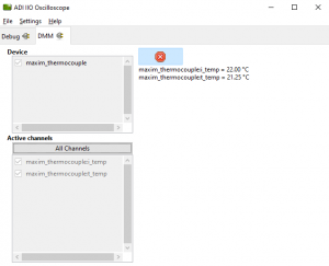
Access the DMM panel to see the instantaneous reading of the thermocouple reading and the device temperature.

PyADI-IIO is a python abstraction module for ADI hardware with IIO drivers to make them easier to use. This module provides device-specific APIs built on top of the current libIIO python bindings. These interfaces try to match the driver naming as much as possible without the need to understand the complexities of libIIO and IIO.
Follow the step-by-step procedure on how to install, configure, and set up PYADI-IIO and install the necessary packages/modules needed by referring to this link.
After installing and configuring PYADI-IIO in your machine, you are now ready to run Python script examples. In our case, run the max31855.py found in the examples folder.
analog@analog:~$ python pyadi-iio/examples/max31855.py serial:<serial port>,57600
In a Windows machine, you can check the port of your MAX32655FTHR and MAX32650FTHR via Device Manager in the Ports (COM & LPT) section. If your device is in COM8, you have to use “python pyadi-iio/examples/max31855.py serial:COM8,57600”.

Github link for the Python sample script: MAX31855 Python Example
Receive software update notifications, documentation updates, view the latest videos, and more when you register your hardware. Register to receive all these great benefits and more!