


This version (20 Apr 2023 03:38) was approved by Richmond Eustacio.The Previously approved version (12 Apr 2023 05:41) is available.
Table of Contents
EVAL-ADT7420-PMDZ Digital Temperature PMOD User Guide
The ADT7420 is a high accuracy digital temperature sensor offering breakthrough performance over a wide industrial range. It contains an internal band gap reference, a temperature sensor, and a 16-bit ADC to monitor and digitize the temperature to 0.0078°C resolution. By default, the ADC resolution is set to 13 bits (0.0625°C). The ADC resolution is a user-programmable and can be changed through the serial interface.
The ADT7420 is guaranteed to operate over supply voltages from 2.7 V to 5.5 V. Operating at 3.3 V, the average supply current is typically 210 μA. This device also has a shutdown mode that powers down the device and offers a shutdown current of typically 2.0 μA at 3.3 V. The ADT7420 is rated for operation over the −40°C to +150°C temperature range.
Pin A0 and Pin A1 are available for address selection, giving the ADT7420 four possible I2C addresses. The CT pin is an open-drain output that becomes active when the temperature exceeds a programmable critical temperature limit. The INT pin is also an open-drain output that becomes active when the temperature exceeds a programmable limit. The INT pin and CT pin can operate in comparator and interrupt event modes.
For general board details and to buy a board, please visit the EVAL-ADT7420-PMDZ product page.

Hardware
This PMOD board is small in size with dimensions approximately 1 inch in width by 1 inch in length.
Power Supply Requirements
When using the EVAL-ADT7420-PMDZ, the 3.3 V power comes directly from the host board it is connected to. The power from the host is generally capable of providing up to 100 mA at 3.3 V, but for complete PMOD power specifications, please click here.
The fastest way to tell if the EVAL-ADT7420-PMDZ board is powered is by seeing if the on-board LED is illuminated. The LED can be found here on the board.

Digital Interface (PMOD)
The PMOD interface is a series of standardized digital interfaces for various digital communication protocols such as SPI, I2C, and UART. These interface types were standardized by Digilent, which is now a division of National Instruments. Complete details on the PMOD specification can be found here.
The specific interface used for the EVAL-ADT7420-PMDZ boards is the extended I2C. In general ADI has adopted the extended I2C connector for all PMOD devices which have an I2C interface. It provides flexibility to add/daisy chain multiple I2C devices onto the same bus.
| P1 Pin Number | Pin Function | Mnemonic |
|---|---|---|
| Pin 1 | Serial Clock | SCL |
| Pin 2 | Serial Clock | SCL |
| Pin 3 | Serial Data | SDA |
| Pin 4 | Serial Data | SDA |
| Pin 5 | Digital Ground | DGND |
| Pin 6 | Digital Ground | DGND |
| Pin 7 | Digital Power | VDD |
| Pin 8 | Digital Power | VDD |
Jumper Configuration and Solder Links
The EVAL-ADT7420-PMDZ has some optional modes of operation to increase flexibility when using multiple EVAL-ADT7420-PMDZ boards in a single system and to help alert the Over/Under/Critical temperature readings. Each configuration is explained below.
ADT7420 I2C Address Selection Pins
The ADT7420 can have up to 4 unique I2C device addresses, depending on the logic level of Pins A1 and A0. The default configuration for the EVAL-ADT7420-PMDZ is for A1 and A0 to be tied low, so the default I2C address is 0x48.

If you decide to change the I2C address, then you need to switch the position of the JP1 and JP2 solder links following the settings in the table below.
| JP1 Solder link Position | JP2 Solder link Position | A1 Logic Level | A0 Logic Level | I2C Device Address(Hex) |
|---|---|---|---|---|
| Pins 2 & 3 Shorted | Pins 2 & 3 Shorted | Low | Low | 0x48 |
| Pins 2 & 3 Shorted | Pins 1 & 2 Shorted | Low | High | 0x49 |
| Pins 1 & 2 Shorted | Pins 2 & 3 Shorted | High | Low | 0x4A |
| Pins 1 & 2 Shorted | Pins 1 & 2 Shorted | High | High | 0x4B |
ADT7420 Over/Under/Critical Temperature Alerts
The ADT7420 has the capability of monitoring temperature and alerting users of Over/Under temperature conditions, as well as Critical temperature events. Access to these pins and functions are provided via the INT and CT connections on the board.

The temperatures are software-configurable, and all you need to do is monitor the INT (for Over/Under temp conditions) or CT (for Critical temp events) with respect to GND.
Device Driver Support
There are two device driver solutions that are provided for controlling the EVAL-ADT7420-PMDZ:
- ADT7420 no-OS Driver
- The MAX32655FTHR example application uses the ADT7420 no-OS drivers and emulates the Linux IIO framework through the tinyiiod daemon library. This driver is used in bare-metal applications, typically running on low-power, embedded microcontrollers. The application communicates with the host computer via the serial backend, over a USB-UART physical connection. This facilitates rapid application development on a host computer, independent from embedded code development.
- ADT7420 Linux Driver
- The ADT7420 Linux driver is used in applications running the Linux operating system, typically on larger processors and SoC devices.
- The ADT7420 Linux driver uses the Industrial Input/Output (IIO) framework, greatly simplifying the development of application code via the cross-platform Libiio library, which is written in C and includes bindings for Python, MATLAB, C#, and other languages. Application code can run directly on the platform board, communicating with the device over the local backend, or from a remote host over the network or USB backends.
System Setup Using ADICUP3029
The EVAL-ADT7420-PMDZ can be used with ADICUP3029.
Demo Requirements
The following is the list of items needed in order to replicate this demo.
- Hardware
- Micro-USB to USB cable
- PC or laptop with USB port
- Software
- Prebuilt ADT7420 Hex File
- Complete ADT7420 Source Files
There are two basic ways to program the ADICUP3029 with the software for the ADT7420.
- Dragging and Dropping the .Hex to the Daplink drive
- Using the drag and drop method, the software is going to be a version that Analog Devices creates for testing and evaluation purposes. This is the EASIEST way to get started with the reference design.
- Building, Compiling, and Debugging using CCES
- Importing the project into CrossCore Embedded Studio is going to allow you to change parameters and customize the software to your application, but will be a bit more advanced and will require you to download the CrossCore toolchain.
Setting up the Hardware
1. Connect EVAL-ADT7420-PMDZ board at connector P9 of the EVAL-ADICUP3029.
2. Connect a micro-USB cable to the P10 connector of the EVAL-ADICUP3029, and then connect it to a computer. The final setup should look similar to the picture below.

3. Make sure the following switches are as shown from the table below.

4. From your PC, open My Computer and look for the DAPLINK drive; if you see this, then the drivers are complete and correct. 
3. Simply extract the provided .zip file. Once extracted, you will see the pre-built hex file for the ADT7420 demo. Then drag and drop this Hex file to the DAPLINK drive and your ADICUP3029 board will be programmed. The DS2 (red) LED will blink rapidly.
4. The DS2 will stop blinking and will stay ON once the programming is done.
5. Temperature readings can be done through a terminal via Putty/Teraterm.
System Setup Using MAX32655FTHR or MAX32650FTHR
The EVAL-ADT7420-PMDZ can be used with the MAX32655FTHR and MAX32650FTHR.
Demo Requirements
The following is the list of items needed in order to replicate this demo.
- Hardware
- MAX32655FTHR or
- MAX32650FTHR with MAX32625PICO
- Micro-USB to USB cable
- 10-pin ribbon cable
- PC or laptop with USB port
- Software
- For MAX32655FTHR,
- Pre-built hex file “adt7420-pmdz_maxim_dummy_example_max32655.hex” in adt7420_max32655fthr.hex
- PuTTY or other similar software
- For MAX32650FTHR,
- Pre-built hex file “adt7420-pmdz_maxim_dummy_example_max32650.hex” in adt7420_max32650fthr.hex
- PuTTY or other similar software
MAX32655FTHR
1. Connect MAX32655FTHR with the FTHR-PMD-INTZ. Note that MAXIM feather board should have stacking headers for feather board where the interposer board will be connected.
2. Connect EVAL-ADT7420-PMDZ to the FTHR-PMD-INTZ.
| EVAL-ADT7420-PMDZ | FTHR-PMD-INTZ |
|---|---|
| Pin 1 and 2 | SCL_PMOD |
| Pin 3 and 4 | SDA_PMOD |
| Pin 5 and 6 | GND |
| Pin 7 and 8 | VCCY_I2C |
The final setup should look similar below.

3. Power up the MAX32655FTHR by connecting it to your laptop using a micro-USB cable.
4. Open the file explorer. Drag-and-drop the pre-built hex file to the DAPLINK. If the transfer was not completed, update the firmware for the DAPLINK. Follow the steps here: https://github.com/MaximIntegrated/max32625pico-firmware-images/
5. Open PuTTY or other similar software. Check the Device Manager to set correct COM for the MAX32655FTHR. Set baud rate to 57600.
The expected output viewed in the PuTTY is shown below.

MAX32650FTHR
1. Using a 10-pin ribbon cable, connect the MAX32625PICO to the MAX32650FTHR.
 2. Connect MAX32650FTHR to the FTHR-PMD-INTZ.
3. Connect EVAL-ADT7420-PMDZ to the FTHR-PMD-INTZ.
| EVAL-ADT7420-PMDZ | FTHR-PMD-INTZ |
|---|---|
| Pin 1 and 2 | SCL_PMOD |
| Pin 3 and 4 | SDA_PMOD |
| Pin 5 and 6 | GND |
| Pin 7 and 8 | VCCY_I2C |
The final setup should look similar below.

4. Power up the MAX32650FTHR by connecting it to your laptop using micro-USB. Connect MAX32625PICO to your laptop as well.
5. Open the file explorer. Drag-and-drop the pre-built hex file to the DAPLINK. If the transfer was not completed, update the firmware for the DAPLINK. Follow the steps here: https://github.com/MaximIntegrated/max32625pico-firmware-images/
6. Open PuTTY or other similar software. Check the Device Manager to set correct COM for the MAX32650FTHR. Set baud rate to 57600.
The expected output viewed in the PuTTY is shown below.

System Setup Using EVAL-ADICUP360 (DEPRECATED)
The original software example for the EVAL-ADT7420-PMDZ was developed on the ADICUP360 platform, and is a simple, terminal-based command line interface. This type of example program is being deprecated in favor of tinyiiod-based servers for embedded platforms, however this example is still available for reference here: ADT7420 Temperature Sensor PMOD Demo on ADICUP360.
Note that the libiio, IIO Oscilloscope, and pyadi-iio sections below do NOT apply to this example.
System Setup Using Raspberry Pi
The EVAL-ADT7420-PMDZ can be used with a Raspberry Pi.
Demo Requirements
The following is a list of items needed in order to replicate this demo.
- Hardware
- Raspberry PI Zero, Zero W, 3B+, or 4
- 16 GB (or larger) Class 10 (or faster) micro-SD card
- 5 Vdc, 2.5 A power supply with micro-USB connector (USB-C power supply for Raspberry Pi 4)
- User interface setup (choose one):
- HDMI monitor, keyboard, mouse plugged directly into Raspberry Pi
- Host Windows/Linux/Mac computer on the same network as Raspberry Pi
- Software
Loading Image on SD Card
In order to boot the Raspberry Pi and control the EVAL-ADT7420-PMDZ, you will need to install ADI Kuiper Linux on an SD card. Complete instructions, including where to download the SD card image, how to write it to the SD card, and how to configure the system are provided on the Kuiper Linux page.
Configuring the SD Card
Follow the configuration procedure under Configuring the SD Card for Raspberry Pi Projects on the Kuiper Linux page, substituting the following lines in config.txt:
dtoverlay=rpi-adt7420
Setting up the Hardware
To set up the circuit for evaluation, consider the following steps:
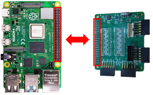
- Connect the P9 of the PMOD to Raspberry Pi Interposer board at the male header GPIO pin connector of the Raspberry Pi as shown below.
- Connect the EVAL-ADT7420-PMDZ on the PMOD to Raspberry Pi Interposer board either via Port P3 or P4.


- Burn the SD card with the proper ADI Kuiper Linux image. Insert the burned SD card on the designated slot on the RPi.
- Connect the system to a monitor using an HDMI cable through the mini HDMI connector on the RPi.
- Connect a USB keyboard and mouse to the RPi through the USB ports.
- Power on the RPi board by plugging in a 5 V power supply with a micro-USB connector. The final setup should look similar to the picture below.

Application Software (All Platforms)
Hardware Connection
The Libiio is a library used for interfacing with IIO devices and is required to be installed on your computer.
Download and install the latest Libiio package on your machine.
To be able to connect your device, the software must be able to create a context. The context creation in the software depends on the backend used to connect to the device as well as the platform where the EVAL-ADT7420-PMDZ is attached. Two platforms are currently supported for the ADT7420: Raspberry Pi using the ADI Kuiper Linux and the ADICUP3029 running the no-OS ADT7420 demo project. The user needs to supply a URI, which will be used in the context creation.
The iio_info command is a part of the libIIO package that reports all IIO attributes.
Upon installation, simply enter the command on the terminal command line to access it.
For RPI Direct Local Access:
iio_info
For Windows machine connected to Raspberry Pi:
iio_info -u ip:<ip address of your ip>
Example:
- If your Raspberry Pi has the IP address 192.168.1.7, you have to use iio_info -u ip::192.168.1.7 as your URI.
Do note that the Windows machine and the RPI board should be connected to the same network in order for the machine to detect the device.
For Windows machine connected to ADICUP3029:
iio_info -u serial:<serial port>
Examples:
- In a Windows machine, you can check the port of your ADICUP3029 via Device Manager in the Ports (COM & LPT) section. If your device is in COM4, you have to use iio_info -u serial:COM4 as your URI.
- In a Unix-based machine, you will see it under the /dev/ directory in this format “ttyUSBn”, where n is a number depending on how many serial USB devices are attached. If you see that your device is ttyUSB0, you have to use serial:/dev/ttyUSB0 as your URI.
IIO Commands
There are different commands that can be used to manage and control the device being used. The iio_attr command reads and writes IIO attributes.
analog@analog:~$ iio_attr [OPTION]...
Example:
- To look at the context attributes, enter this code on the terminal:
analog@analog:~$ iio_attr -a -C
The iio_reg command reads or writes SPI or I2C registers in an IIO device. This is generally not needed for end applications but can be useful in debugging drivers. Note that you need to specify a context using the -u qualifier when you are not directly accessing the device via RPI or when you are using the ADICUP3029 platform.
analog@analog:~$ iio_reg -u <context> <device> <register> [<value>]
Example:
- To read the device ID (register = 0x02) of an ADT7420 interfaced via RPI from a Windows machine, enter the following code on the terminal:
iio_reg -u ip:<ip address> adt7420 0x02
IIO Oscilloscope
Make sure to download/update to the latest version of IIO Oscilloscope found on this linkhttps://github.com/analogdevicesinc/iio-oscilloscope/releases
- Once done with the installation or an update of the latest IIO Oscilloscope, open the application. The user needs to supply a URI, which will be used in the context creation of the IIO Oscilloscope and the instructions can be seen in the previous section.
- Press refresh to display available IIO Devices, once ADT7420 appeared, press connect.

Debug Panel
Below is the Debug panel of ADT7420 wherein you can directly access the device attributes.

DMM Panel
Access the DMM panel to see the instantaneous reading of the ADT7420 temperature reading.

PyADI-IIO
PyADI-IIO is a Python abstraction module for ADI hardware with IIO drivers to make them easier to use. This module provides device-specific APIs built on top of the current libIIO Python bindings. These interfaces try to match the driver naming as much as possible without the need to understand the complexities of libIIO and IIO.
Follow the step-by-step procedure on how to install, configure, and set up PYADI-IIO and install the necessary packages/modules needed by referring to this link.
Running the example
After installing and configuring PYADI-IIO in your machine, you are now ready to run python script examples. In our case, run the adt7420_example.py found in the examples folder.
For No-OS
At line 38 of the example python script, the COM indicated should be updated based on your device. In a Windows machine, you can check the port of your MAX32655FTHR and MAX32650FTHR via Device Manager in the Ports (COM & LPT) section. If your device is in COM18, line 38 should be:
temp_sensor = adi.adt7420(uri="serial:COM18,57600,8N1")
To run the example python script, iio example hex should be loaded in the maxim platform before running the line below:
D:\pyadi-iio\examples>python adt7420_example.py
Press enter and you will get these readings.

Github link for the Python sample script: ADT7420 Python Example
More information and useful links
Schematics, PCB Layout, Bill of Materials
EVAL-ADT7420-PMDZ Design & Integration Files
- Schematic
- PCB Layout
- Bill of Materials
- Allegro Project
Additional Information
Registration
Receive software update notifications, documentation updates, view the latest videos, and more when you register your hardware. Register to receive all these great benefits and more!
End of Document
resources/eval/user-guides/circuits-from-the-lab/eval-adt7420-pmdz.txt · Last modified: 20 Apr 2023 03:38 by Richmond Eustacio