


This version (30 Nov 2021 19:49) was approved by Brandon Bushey.The Previously approved version (23 Nov 2021 09:00) is available.
Table of Contents
CN0534 Evaluation Board Guide
Overview
The International Telecommunication Union (ITU) allocates the un-licensed 5.8 GHz industrial, scientific, and medical (ISM) radio frequency band for use worldwide. Advancements in wireless technologies and standards, as well as minimal regulatory compliance requirements, have made this frequency band popular for short range, wireless communication systems.
The 5.8 GHz band is preferred for short range digital communication applications (such as WiFi) because of the number of channels and the bandwidth available. While the transmission range is short-er than that of the 2.4 GHz band, its 150 MHz bandwidth accommodates up to 23 non-overlapping WiFi channels. Additional com-mon uses include software defined radio, wireless access points, public safety radio, wireless repeaters, femtocells, and Long-Term Evolution (LTE)/Worldwide Interoperability for Microwave Access (WiMAX)/4G, base transceiver station (BTS) infrastructure.
This design provides high gain, robust overpower monitoring, and protection all in a small footprint, which is a great addition to any ISM band application where low signal strength or distance may be a complication.
The circuit is a high performance RF receiver system with +23 dB of gain, optimized for operation at a center frequency of 5.8 GHz. The input is unfiltered, maintaining a noise figure of 2 dB, while a bandpass filter at the output attenuates out-of-band interferers.
The circuit includes a high speed overpower detector and switch that protects sensitive downstream equipment connected to the receiver system. The receiver system also automatically returns to normal operation when the RF power level drops within the acceptable range. The RF inputs and outputs are standard SMA connectors, and the entire design is powered from a single micro USB connector.


General Setup


LED, DS1 from CN0534, will automatically turn on indicating that the CN0534 is powered and operational. If the LED is off, the CN0534 could still be powered properly, but the RF input power into the amplifier might be activating the automatic shutdown, so try to lower the RF input signal by 10dB and see if the LED turns on.
Connectors

SMA Connectors
The SMA connectors are used for the RF input and output connections.
- J1 is the RF OUTPUT SMA Female connector that would normally be connected to a radio or piece of RF equipment.
- J2 is the RF INPUT SMA Male connector that would normally be connected to an antenna.
Power Connector
- P1 is the micro USB port used to provide 5V power to the board
Getting Started
Required Equipment
- Two (2) micro-USB power adaptors OR Two (2) micro-USB to USB cables for powering up ADALM-Pluto and EVAL- CN0534-EBZ
- One (1) SMA male to SMA male cable
- One (1) SMA 10dB RF Attenuator (6610_SMA-50-2/199_NE) OR any equivalent RF Attenuator with same attenuation or higher
ADALM-Pluto Preparation
Firmware Loading
- Download Pluto firmware 0.30 version
- Unzip downloaded folder.
- Connect Pluto to PC/Laptop using micro USB cable in the terminal with USB symbol.
- Open the Pluto mass storage device.
- Open the downloaded firmware file.
- Copy the file, pluto.frm, to the Pluto mass storage device

- This will cause LED1 to blink rapidly. This means programming is taking place. Do not remove power (or USB) while the device is blinking rapidly. It does take approximately 4 minutes to properly program the device.
- Once the device is done programming, it will re-appear as a mass storage device.
- Eject (don't unplug) the Pluto mass storage device.

- Now the usb cable can now be safely disconnect in PC.


Updating to the AD9364
- Connect again the Pluto to PC/Laptop using micro USB cable.
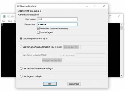
- Open any serial application (ex. TeraTerm, Putty) and ssh to 192.168.2.1, username is root and the password is analog.

- To change things to the AD9364 configuration, type in the following commands, line by line:
# fw_setenv attr_name compatible
# fw_setenv attr_val ad9364
# reboot

- Eject (don't unplug) the Pluto mass storage device.
- Now the usb cable can now be safely disconnect in PC.
- Connect again Pluto to PC/Laptop using micro USB cable and proceed setting up the hardware test setup following the instruction in the next section.


Test Setup
Normal Operation

- Connect the RF TX of Pluto SDR to J2 of the EVAL-CN0534-EBZ Board
- Connect J1 of the EVAL-CN0534-EBZ Board to the RF RX of Pluto SDR
- Connect P1 (micro USB) connector of the EVAL-CN0534-EBZ Board into a PC USB port or 5V USB charger.
- The DS1 LED of CN0534 will automatically turn on indicating the board is powered on and is in operation.
The ADALM-Pluto can be configured using an IIO Oscilloscope, visit the website on
- IIO Oscilloscope to know more about the tool.
- Optional: an RF attenuator can be connected in between the EVAL-CN0534-EBZ Board RF Output and the RF RX of Pluto SDR to protect the RX of Pluto from exceeding its limits.
IIO Oscilloscope
Make sure to download/update to the latest version of IIO-Oscilloscope found on this linkhttps://github.com/analogdevicesinc/iio-oscilloscope/releases
- Once done with the installation or an update of the latest IIO-Oscilloscope, open the application. The user needs to supply a URI which will be used in the context creation of the IIO Oscilloscope and the instructions can be seen from the previous section.
- Press refresh to display available IIO Devices, once ADALM-Pluto appeared, press connect.

ADALM Pluto Loop-Back Operation
 The plot shown below is the ADALM Pluto output with the RF TX and RX connected directly with transmit power set to -30 dBFS producing a 63.5 dB RSSI RF power input reading:
 And with transmit power set to -10 dBFS producing a 43.5 dB RSSI RF power input reading:

Normal Operation
 The plot is as shown below with transmit power set to -30 dBFS producing a 41.5 dB RSSI RF power input reading providing a gain of 22dB in reference with the loop back test operation:

Auto Shutdown Operation
The plot is as shown below with transmit power set to -10 dBFS producing a 40.25 dB RSSI RF power input reading and showing a 20 dB attenuation in reference with the loop back test operation:

WARNING
Connecting the EVAL-CN0534-EBZ Board directly to the input (Rx) of a radio or other piece of RF equipment may exceed the absolute maximum ratings for the RF Input. (which is +2.5 dBm for the ADALM-PLUTO). Doing this may permanently damage the input.
 Never do this in normal operation.
More Information and Useful Links
Schematic, PCB Layout, Bill of Materials
EVAL-CN0534-SDPZ Design & Integration Files
- Schematics
- PCB Layout
- Bill of Materials
- Gerber Files
- Allegro Board File
End of Document
resources/eval/user-guides/circuits-from-the-lab/cn0534.txt · Last modified: 30 Nov 2021 19:49 by Brandon Bushey