The EVAL-CN0523-EBZ is a USB-powered, RF power amplifier that is optimized for transmitting signal chains in the 5.8 GHz ISM band. Using two HMC407 amplifiers cascaded together, the design provides a gain of 28 dB and return losses of more than 10 dB throughout its RF band of operation.
An overtemperature management feature is implemented on the EVAL-CN0523-EBZ wherein the amplifiers are automatically disabled when the board temperature reaches a preset threshold, and it automatically returns to normal operation once the temperature falls below the hysteresis point.
Designed to be used with the ADALM-PLUTO, or other software defined radio platform, the board features a small form factor, with dimensions of 25.4 mm × 50.8 mm x 1.5748 mm (PCB only). The RF input and output are designed with a 50 Ω impedance, enabling direct connection between the circuit and standard 50 Ω systems.
A micro-USB connector is used for the input power, allowing the evaluation board to use most +5 V wall wart power supplies available in the market.
 Figure 1. EVAL-CN0523-EBZ Block Diagram
| LED Indications of Board Status | ||
|---|---|---|
| DS1 | DS2 | Board Status |
| Off | Off | No power |
| Off | On | Normal operation |
| On | On | Overtemperature |
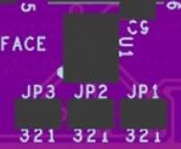
 Figure 4. ADT6401 Jumper Setting
| Selecting a Trip Point for the ADT6401 | ||||
|---|---|---|---|---|
| JP1 Setting | JP2 Setting | JP3 Setting | Trip Point | Hysteresis |
| 2 & 3 | 2 & 3 | 2 & 3 | +45°C | 2°C |
| 1 & 2 | 2 & 3 | 2 & 3 | +55°C | 2°C |
| No solder jumper | 2 & 3 | 2 & 3 | +65°C | 2°C |
| 2 & 3 | 1 & 2 | 2 & 3 | +75°C | 2°C |
| 1 & 2 | 1 & 2 | 2 & 3 | +85°C | 2°C |
| No solder jumper | 1 & 2 | 2 & 3 | +95°C | 2°C |
| 2 & 3 | 2 & 3 | 1 & 2 | +65°C | 10°C |
| 1 & 2 | 2 & 3 | 1 & 2 | +75°C | 10°C |
| No solder jumper | 2 & 3 | 1 & 2 | +85°C | 10°C |
| 2 & 3 | 1 & 2 | 1 & 2 | +95°C | 10°C |
| 2 & 3 | No solder jumper | 2 & 3 | +105°C | 2°C |
| 1 & 2 | No solder jumper | 2 & 3 | +115°C | 2°C |
| No solder jumper | No solder jumper | 2 & 3 | +55°C | 10°C |
Due to the considerable thermal dissipation of the RF amplifiers, the last three options should not be used.
ADALM-PLUTO Firmware
 Figure 5. EVAL-CN0523-EBZ Test Setup
Warning: Connecting the CN0523 directly to the PlutoSDR input (Rx) may result in an exceedance of its absolute maximum ratings of +2.5 dBm. Such an action may lead to permanent damage to the PlutoSDR. It is strongly recommended to use a 30 dB or 40 dB attenuator at the RX input of the ADALM PLUTO to avoid incurring damage.
EVAL-CN0523-EBZ Design & Integration Files
Receive software update notifications and documentation updates, view the latest videos, and more when you register your hardware. Register to receive all these great benefits and more!
End of Document