


No renderer 'pdf' found for mode 'pdf'
This version (20 Nov 2023 03:12) was approved by Joyce Velasco.The Previously approved version (30 Jul 2021 07:21) is available.
Table of Contents
CN0206 -- Complete Type T Thermocouple Measurement System with Cold Junction Compensation (DEPRECATED)
This particular reference design has been RETIRED or DEPRECATED, which means it is no longer supported. This page is here for historical/reference purposes only.
Overview
This circuit is a complete thermocouple system based on the AD7793 24-bit sigma-delta analog-to-digital converter (ADC). The AD7793 is a low power, low noise, complete analog front end for high precision measurement applications. The device includes a programmable gain amplifier (PGA), an internal reference, an internal clock, and excitation currents, thereby greatly simplifying the thermocouple system design.
The AD7793 consumes only 500uA maximum, making it suitable for any lower power application, such as smart transmitters where the complete transmitter must consume less than 4mA.
Because the AD7793 provides an integrated solution for thermocouple design, it interfaces directly to the thermocouple. For the cold junction compensation, a thermistor along with a precision resistor is used. There are the only external components required for the cold junction measurement other than some simple RC filters for EMC considerations.
General Setup
- EVAL-CN0206-SDPZ Evaluation board.
- One SDP Controller board:
- EVAL-SDP-CS1Z SDP Evaluation board
- EVAL-SDP-CB1Z SDP Evaluation board
- 1 USB Type-A plug to USB Mini-B plug cable
- 1 Six Volt DC Wall Wart ( EVAL-CFTL-6V-PWRZ)
- 1 Thermocouple Source (Tester used in this guide is the Omega CL540ZA)
- 1 T-type Thermocouple Wire (Cable used in this guide is the Omega CL-300-CABLE-T-2)
Minimum PC/System Requirements
- One PC with the following
- Windows XP SP2, Windows Vista or Windows 7 Business/Enterprise/Ultimate editions
- Intel Pentium processor (x86 compatible), 1GHz or faster
- 512 MB RAM and 2 GB available hard disk space
- .NET 3.5 Framework
How to Install the Evaluation Software
- Extract the files within the file CN0206 SDP Eval Software.zip and open the file setup.exe. It is recommended that you install the CN0206 SDP Evaluation Software to the default directory path C:\Program Files\Analog Devices\CN0206\ and all National Instruments products to C:\Program Files\National Instruments\

- Press “Next”.

- Press “Next”.

- Press “Next”.
- Upon completion of the installation of the CN0206 SDP Eval Software, the installer for the ADI SDP Drivers will execute. Follow the on-screen prompts to install the drivers. It is recommended that you close all other applications before clicking “Next”. This will make it possible to update relevant system files without having to reboot your computer. It is recommended that you install the drivers to the default directory path C:\Program Files\Analog Devices\SDP\Drivers\

- Press “Next”.

- Press “Finish” to install the Drivers and complete the installation of all software necessary to evaluate the EVAL-CN0206-SDPZ
Step by Step Instruction for Connecting the Hardware
- Connect the EVAL-SDP-CS1Z and the EVAL-CN0206-SDPZ PCB’s using the 120 pin male and female connectors found on the respective boards.

- Plug the mini end of the USB cable into connector J2 of the EVAL-SDP-CS1Z and connect the other end of the USB cable into the Laptop or PC.

- Plug in the wall wart and connect it to connector J2 of the EVAL-CN0206-SDPZ.
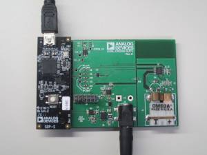
- Plug one end of the t-type thermocouple wire into the thermocouple source.

- Plug the second end of the t-type thermocouple wire into connector J1 on the EVAL-CN0206-SDPZ.
- Line up the colors of the metal on the male end with the colors of the metal on the female end.
Opening and Enabling the Evaluation Software
- Launch the executable found at C:\Program Files\Analog Devices\CN0206 and press the “Connect“ button.

- After pressing the “Connect” button, a prompt will appear informing the user if the ADC was properly configured. Press “Ok” and the software is ready to use. If the ADC is not configured properly, disconnect the entire setup and start over.

Step by Step Instruction to Using the Evaluation Software
- The following is a list of all available software controls and displays, grouped according to their location in the software:
- System Controls
- Connect – This button configures the AD7793 by writing to the necessary registers. A prompt will appear informing the user if the ADC was properly configured.
- Disconnect – This button will disconnect the EVAL-CN0206-SDPZ board.
- Data Acquisition Controls
- # of Samples – This control determines the number of samples displayed on the chart found in the main tab of the evaluation software.
- Acquire Samples- This button polls the data ready bit in the AD7793 status register. When this bit is set, LabVIEW reads the data registers and displays the temperature data on the chart found in the evaluation software.
- Save Data to File – This button saves all data displayed in the LabVIEW chart.
- Clear Data – This button clears all data displayed in the LabVIEW chart.
- Main Tab - This tab contains displays for the Sampled Data, Histogram, Calibration Procedure and Administration purposes.
- Sample Data - This page contains a waveform chart visually displaying the temperature readings taken after clicking the Acquire Samples button.
- Histogram - This page contains a histogram allowing the user to see the distribution of codes for a particular input temperature.
- Calibration - This page contains the controls necessary to calibrate the entire thermocouple system using a two-point linear interpolation.
- Calibrate - This button will calculate the calibration coefficients based on two data points gathered on the Sampled Data page.
- Data Point One - The first data point is (Input Temp1, Output Temp1).
- Input Temp1 - This is the input temperature set by the thermocouple source (i.e -180°C).
- Output Temp1 - This is the output temperature conversion from the ADC.
- Data Pint Two - The second data point is (Input Temp2, Output Temp2).
- Input Temp2 - This is the input temperature set by the thermocouple source (i.e 380°C)
- Output Temp2 - This is the output temperature conversion from the ADC.
- Delete Calibration - This button will delete the calibration coefficients by writing '0' to the offset and '1' to the gain. Any samples taken without calibrating will produce results with significant errors.
- Administration - This page provides access to several controls for the EVAL-SDP-CS1Z or EVAL-SDP-CB1Z controller board.
- SCLK (Hz) - This control allows the user to change the SPI interface clock frequency.
- FS (Hz) - This control allows the user to change the SPI interface frame frequency.
- Select SDP Connector - This control allows the user to select which connector is utilized on the EVAL-SDP-CB1Z
- Read Firmware - This control allows the user to read the firmware information from the SDP controller board.
- Flash LED - This control allows the user to flash the LED found on the SDP controller board.
Calibration
- This section explains the steps required to properly calibrate the EVAL-CN0206-SDPZ thermocouple system.
- Navigate to the Calibration Page on the Main Tab. PICTURE HERE
- In Data Acquisition Controls, set the # of Samples to 1.
- Navigate to the Data Sampling page in the main tab.
- Set the thermocouple source to -180°C (This is Input Temp 1) and press the Acquire Samples button found in the Data Acquisition Controls.
- Observe the temperature reading in the digital display below the chart (This is Output Temp1)
- Repeat steps one through four but make Input Temp2 350°C.
- Navigate back to the Calibration Page on the Main Tab and press Calibrate. This will complete the two point calibration and any future samples converted by the ADC will automatically be corrected.
- The thermocouple response is non-linear and depending on the temperature range of interest, the calibration inputs can be changed by the user to provide different results.
Registration
Receive software update notifications, documentation updates, view the latest videos, and more when you register your hardware. Register to receive all these great benefits and more!
End of document
resources/eval/user-guides/circuits-from-the-lab/cn0206.txt · Last modified: 20 Nov 2023 03:12 by Joyce Velasco