


This version (18 Mar 2024 22:01) was approved by Sam Ringwood.
Table of Contents
ADXBAND16EBZ Prototyping Platform User Guide
Product Details
The Triton Quad-Apollo System Development Platform contains four AD9084 software defined, direct X-Band Quad-MxFE, as well as associated RF front-ends, clocking, and power circuitry. The target application is phased array radars, electronic warfare, and ground-based SATCOM, specifically a 16 transmit/16 receive channel direct X-Band sampling phased array at L/S/C/X-Band (0.1 GHz to ~12GHz). The Rx & Tx RF front-end has drop-in configurations that allow for customized frequency ranges up to Ku-Band (12-18GHz), depending on the end user’s application.
The ADXBAND16EBZ System Development Platform highlights a complete system solution. It is intended as a testbed for demonstrating multi-chip synchronization as well as the implementation of system level calibrations, beamforming algorithms, and other signal processing algorithms. The system is designed to mate with a VCU118 Evaluation Board from Xilinx®, which features the Virtex® UltraScale+™ XCVU9P FPGA, with provided reference software, HDL code, and MATLAB system-level interfacing.
In addition to the ADXBAND16EBZ Digitizing Card, the kit also contains a 16Tx/16Rx Calibration Board that is used to develop system-level calibration algorithms, or otherwise more easily demonstrate power-up phase determinism in situations pertinent to their own use case. The Calibration Board also allows the user to demonstrate combined-channel dynamic range, spurious, and phase noise improvements and can also be controlled via MATLAB add-on when connected to the PMOD interface of the VCU118.
The system can be used to enable quick time-to-market development programs for applications like:
- ADEF (Phased-Array, RADAR, EW, SATCOM)
- Communications Infrastructure (Multiband 5G and mmWave 5G)
- Electronic Test and Measurement

Video Demo
Features
- Multi-channel, wideband system development platform for the AD9084 en/products/ad9084.html
- Mates with Xilinx VCU118 Evaluation Board (Not Included)
- 16x RF Receive (Rx) Channels (32x Digital Rx Channels)
- Total 16x 4GSPS to 20GSPS ADC
- 48x Digital Down Converters (DDCs), Each Including Complex Numerically-Controlled Oscillators (NCOs)
- 16x Programmable Finite Impulse Response Filters (pFIRs)
- 16x RF Transmit (Tx) Channels (32x Digital Tx Channels)
- Total 16x 4GSPS to 28GSPS DAC
- 48x Digital Up Converters (DUCs), Each Including Complex Numerically-Controlled Oscillators (NCOs)
- Flexible Rx & Tx RF Front-Ends
- Rx: Filtering, Amplification, Digital Step Attenuation for Gain Control
- Tx: Filtering, Amplification
- Multiple System Control and Analysis Tools
- IIO Oscilloscope GUI
- MATLAB Add-Ons & Example Scripts
- HDL and Embedded Software Solutions for JESD204B/JESD204C Bring-Up
- Provided Application-Specific Examples
- Multi-Chip Synchronization for Power-Up Phase Determinism
- System-Level Amplitude/Phase Alignment Using NCOs
- Low-Latency ADC-to-DAC Loopback Bypassing JESD Interface
- pFIR Control for Broadband Channel-to-Channel Amplitude/Phase Alignment
- Fast-Frequency Hopping
- On-Board Power Regulation from Single 12V Power Adapter (Included)
- 315-Watt Max Power Consumption
- Flexible Clock Distribution
- Single-ended 400MHz (0dBm) Clock Reference input required ADF4382 (4x) Reference Clock Distribution
- Support for External Converter Clock
- High channel density in X-Band Lattice Spacing Form Factor
- SYSREF Distribution for Multi-Chip Synchronization
- Multiple Frequency Bands (12.8GSPS)
- 8 – 12GHz Rx/ 8 – 12GHz Tx (ADXBAND16EBZ, 4x AD9084)
- Ethernet & USB Interfaces
General Description
This user guide serves as the main source of information for system engineers and software developers using the ADXBAND16EBZ System Evaluation Board, which contains four AD9084 software defined, direct X-Band Sampling Phased Array Development Platform, as well as associated RF front-end, clocking, and power circuitry. The target application is phased array radars, electronic warfare, and ground-based SATCOM, specifically a 16 transmit/16 receive channel direct X-Band sampling phased array at L/S/C/X-Band (0.1 GHz to ~12GHz). The Rx RF front-end has by-pass configurations that allow for customized frequency ranges up to Ku-band, depending on the end user’s application.
The ADXBAND16EBZ System Evaluation Board highlights a complete system solution. It is intended as a testbed for demonstrating multi-chip synchronization as well as implementation of system level calibrations, beam forming algorithms, and other signal processing algorithms. The board is designed to mate with a VCU118 Evaluation Board from Xilinx®, which features the Virtex® UltraScale+™ XCVU9P FPGA, with provided reference software and HDL code.
High-Level Block Diagram

Calibration Board
ADXBAND16EBZ-CAL Digitizing Card Key Features:
• Provides both individual adjacent channel loopback and combined channel loopback options
• Combined Tx and Rx channels output via SMPM connectors

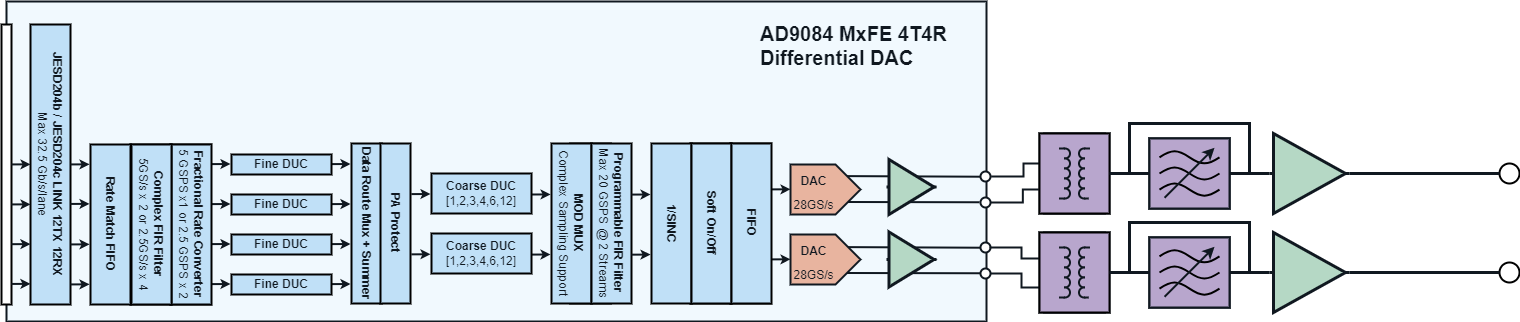
Triton Signal Chain

Multi-Chip Synchronization
A 4-step process allows single clock synchronization across dozens of channels using a tree fan-out architecture for bi-directional SYSREF

Combined Channel Performance
Combining 16 Tx channels after phase alignment improves Power Magnitude ~23dBm with SFDR improving by ~18dB
Combining 16 Rx channels after phase alignment improves NSD performance ~12dB with SFDR improving by >11dB


Publications
- Prior Generation Quad MxFE: Power-Up Phase Determinism Using Multichip Synchronization Features in Integrated Wideband DACs and ADCs
Related Part Pages
AD9084
ADF4382A
ADL8102
ADL8100
ADMV8913
ADRF5730
ADF4351
LTC6953
LTC6952
LT8627SP
LTM8060
LTM4709
LTM8074
FPGA Evaluation Board Hardware
Questions
For additional questions or support, please visit the Engineering Zone forum at adef.
resources/eval/user-guides/adxband16ebz.txt · Last modified: 18 Mar 2024 22:01 by Sam Ringwood