Analog Devices uses six designations to inform our customers where a semiconductor product is in its life cycle. From emerging innovations to products which have been in production for twenty years, we understand that insight into life cycle status is important. Device life cycles are tracked on their individual product pages on analog.com, and should always be consulted before making any design decisions.
This particular articl/edocument/design has been retired or deprecated, which means it is no longer maintained or actively updated, even though the devices themselves may be Recommended for New Designs or in Production. This page is here for historical/reference purposes only.
The majority of the parts are accessible via SPI. To keep inside the LPC form factor, the board uses a micro-controller as an I2C to SPI bridge (SPI chip selects would have pushed things over the LPC pin count).
The reference design SDK sample program provides general spi read and write access. It is possible to expand the access for burst mode.
| FMC connector | I2C Slave Address |
|---|---|
| HPC | 0x58 |
| LPC | 0x59 |
| Name | Chip Select | SPI Mode | Comment |
|---|---|---|---|
| AD8366 | 6 | SPI_MODE_0, SPI_3WIRE | VGA |
| AD9122 | 0 | SPI_MODE_0 | DAC |
| AD9523 | 3 | SPI_MODE_0, SPI_3WIRE | Clock-Dist |
| AD9548 | 2 | SPI_MODE_0, SPI_3WIRE | Clock-Sync |
| AD9643 | 1 | SPI_MODE_0, SPI_3WIRE | ADC |
| ADF4351 | 4 | SPI_MODE_0 | RX PLL |
| ADF4351 | 5 | SPI_MODE_0 | TX PLL |
This must be done before a read or write:
I2C Address (Write) | 0x03 | spi_settings[15:8] | spi_settings[7:0] | chip_select[15:8] | chip_select[7:0] |
I2C Address (Write)| 0x04 | data | data | data (up to 62 bytes at once)
I2C Address (Read) | data |data | data (up to 62 bytes at once)
I2C Address (Write) | 0x01
After sending this command the PIC firmware version can be read by issuing an I2C read command for 32 bytes of data.
[15:10] Rx Transfer count, this is the number of bytes that will be read from the selected SPI slave
[6]     3-Wire/4-Wire Count
           1 = 3-Wire
           0 = 4-Wire
[5]     CS state at end of transfer
           1 = CS goes high
           0 = CS remains low
[4]     Sample bit
           1 = Input data sampled at end of data output time
           0 = Input data sampled at middle of data output time
[3]     Clock Select
           1 = Transmit occurs on transition from active to idle clock state
           0 = Transmit occurs on transition from idle to active clock state
[2]     Clock Polarity
           1 = Idle state for clock is high
           0 = Idle state for clock is low
[1:0]   SPI Clock
           11 = Invalid
           10 = Fosc / 64
           01 = Fosc / 16
           00 = Fosc / 4
And chip_select is 2^(chip select-1). This is a bitmap.
This allows to address multiple parts at once.
So the first chip select is 0x0001, the second is 0x0002, the third is 0x0004, etc.
#define SPI_XCOMM_SETTINGS_LEN_MASK		(0x3f << 10)
#define SPI_XCOMM_SETTINGS_3WIRE		BIT(6)
#define SPI_XCOMM_SETTINGS_CS_HIGH		BIT(5)
#define SPI_XCOMM_SETTINGS_SAMPLE_END		BIT(4)
#define SPI_XCOMM_SETTINGS_CPHA			BIT(3)
#define SPI_XCOMM_SETTINGS_CPOL			BIT(2)
#define SPI_XCOMM_SETTINGS_CLOCK_DIV_MASK	0x3
#define SPI_XCOMM_SETTINGS_CLOCK_DIV_64		0x2
#define SPI_XCOMM_SETTINGS_CLOCK_DIV_16		0x1
#define SPI_XCOMM_SETTINGS_CLOCK_DIV_4		0x0

#define SPI_XCOMM_CMD_TEST		0x02
#define SPI_XCOMM_CMD_UPDATE_CONFIG	0x03
#define SPI_XCOMM_CMD_WRITE		0x04
#define SPI_XCOMM_CMD_GPIO_SET		0x05
The PIC firmware is not open source (sorry). It is released as a Hex file on Github.
| Release Date | Version | Reason |
|---|---|---|
| Aug 01, 2012 | 1 | First version. |
| Dec 05, 2012 | 2 | Minor speed (I2C) improvements. |
| Jul 01, 2013 | 3 | Fixed an EEPROM problem that causes data update issues. Stored the PIC firmware version to EEPROM. |
Periodically - we do update the PIC firmware for fixes/enhancements - Unless you are specifically running into one of these problems which are resolved - DO NOT UPDATE. There is no on-board way to update, and it does require a low cost USB programmer. It does not use a standard pinout either. It's a pain, since we do NOT want you to update things.
For those people who feel compelled, the instructions are below:
The microcontroller on the board is a Microchip PIC18F24J50-I/ML. You should select this device in your programmer. There are many programmers available for this device. We use a variety, depending on the development location.
Do not update the PIC without saving the calibration and FRU information (so you can restore it). Updating the PIC code will erase this information. It's a simple matter to do (This assumes you are using the Linux design - there isn't way to do this for the no-OS infrastructure):
root@linaro-ubuntu-desktop:~# for eeprom in $(find /sys -name eeprom); do cat $eeprom > $(echo $eeprom | sed 's:/:_:g') ; done
Check to make sure the files are there properly (they should be 256 bytes each):
root@linaro-ubuntu-desktop:~# ls -l _sys*
-rw-r--r-- 1 root root 256 Jan  1 00:04 _sys_devices_amba.1_41600000.i2c_i2c-1_1-0050_eeprom
-rw-r--r-- 1 root root 256 Jan  1 00:04 _sys_devices_amba.1_41600000.i2c_i2c-1_1-0054_eeprom
and then update, when done updating, just re-write the contents:
root@linaro-ubuntu-desktop:~# for eeprom in $(ls _sys*) ; do cat $eeprom > $(echo $eeprom | sed 's:_:/:g') ; done
To make sure things are OK, try:
root@linaro-ubuntu-desktop:~# find /sys/ -name eeprom
/sys/devices/amba.1/41600000.i2c/i2c-1/1-0050/eeprom
/sys/devices/amba.1/41600000.i2c/i2c-1/1-0054/eeprom
root@linaro-ubuntu-desktop:~# cat /sys/devices/amba.1/41600000.i2c/i2c-1/1-0050/eeprom | hexdump -C
00000000  01 00 00 01 00 09 00 f5  01 08 19 0e d3 88 ce 41  |...............A|
00000010  6e 61 6c 6f 67 20 44 65  76 69 63 65 73 cb 46 4d  |nalog Devices.FM|
00000020  43 20 43 6f 6d 6d 73 20  31 c7 64 34 36 33 32 31  |C Comms 1.d46321|
00000030  32 cf 41 44 2d 46 4d 43  4f 4d 4d 53 31 2d 45 42  |2.AD-FMCOMMS1-EB|
00000040  5a c0 c2 00 42 c1 00 ad  02 02 0d 58 97 00 fa 00  |Z...B......X....|
00000050  b4 00 fa 00 00 00 00 00  00 00 02 02 0d 5b 94 01  |.............[..|
00000060  4a 01 29 01 6b 01 00 00  00 00 b8 0b 02 02 0d f6  |J.).k...........|
00000070  f9 02 b0 04 38 04 28 05  00 00 00 00 e8 03 01 02  |....8.(.........|
00000080  0d fd f3 03 00 00 00 00  00 00 00 00 00 00 00 00  |................|
00000090  01 02 0d fc f4 04 00 00  00 00 00 00 00 00 00 00  |................|
000000a0  00 00 01 02 0d fb f5 05  00 00 00 00 00 00 00 00  |................|
000000b0  00 00 00 00 fa 02 0b fc  fd a2 12 00 00 0c 44 00  |..............D.|
000000c0  00 00 00 00 fa 82 04 3c  44 a2 12 00 10 ff ff ff  |.......<D.......|
000000d0  ff ff ff ff ff ff ff ff  ff ff ff ff ff ff ff ff  |................|
*
00000100

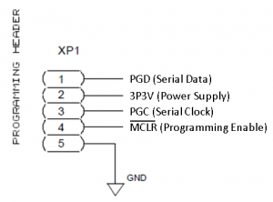
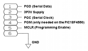
 The FMComms1 board (left) uses a non-standard pinout for the PIC programming. It is on a 0.1 inch header with the configuration shown. This is almost the same as the program header found on the ADI DAC boards, shown on the right (if you have one of those cables, it's pretty easy to snip pin 4 out, and make it work). It's up to you to make sure the part is properly connected and programmed properly.